So recently I started to read about error detection, that how error detection started and implemented,
But wait—what kind of errors are we dealing with? Lets take an example of ECC RAM (Error-Correcting Code RAM). Unlike the RAM in your laptop, which can afford the occasional unnoticed error, ECC RAM actively fixes mistakes in real-time—because in places like banks and space missions, even a single corrupted bit could mean disaster.
Lets take an example
Let’s say a server is storing financial transactions in RAM. You might think errors happen due to faulty hardware or software bugs and it should be fixable normally, whats the big deal?
But sometimes, errors don’t come from faulty code or bad hardware—they come from something you cant control like outer space!! A random bit flip occurs due to cosmic radiation.
Cosmic rays are high-energy particles from space (mainly protons) that constantly hit Earth. When they strike electronic components, they can knock electrons loose, causing bit flips in memory. This is called a Single Event Upset (SEU).
So due to cosmic radiation the stored amount $1000 (binary 1111101000) accidentally becomes $1008 (binary 1111101100). Just a single bit got flipped and hence it changed the amount saved in the system. That’s a serious problem—imagine this happening thousands of times across a banking system.
A bit of history..
So in 1940s there was an American mathematician and Engineer Richard Hamming who was working at Bell Labs and used to access a complex punch card computer, and the programs that he used to pass through kept failing because of the random error which used to flip a bit and the whole program used to crash.
Frustrated by unintentional errors caused by factors beyond human control (like cosmic radiation), he developed the first error correction code.
Parity Checks
Before talking about hamming's algorithm there is some context we need to have about parity checks, because its used heavily in Hamming's algorithm. The idea of Parity checks is pretty simple but cool. To understand Parity Checks lets take an example
Let’s say we need to transmit a 7-bit message, and its binary representation looks like this: - 1101010 , now, when the receiver gets this message, how do they know whether it was transmitted correctly or if an error occurred?
To help with this, a parity bit is added to the message. Instead of sending just 7 bits, we send 8 bits, where one extra bit is included purely for error detection.
Even Parity Check
One common method is the even parity check, where:
- We count the number of
1sin the message. - If the number of
1sis odd, we add a1as the parity bit to make the total count even. - If the number of
1sis already even, we add a0as the parity bit to keep it even.
For example, in our message 1101010, the number of 1s is four (which is already even). So, the parity bit added will be 0:
Original message:  1101010
Parity bit:        0
Transmitted data:  11010100
If instead the message was 1101011 (which has five 1s), we would add a 1 to make it even:
Original message:  1101011
Parity bit:        1
Transmitted data:  11010111
Error Detection with Parity Checks
After transmission, the receiver recounts the number of 1s.
- If the total count is even, the message is considered correct.
- If the total count is odd, it means an error occurred during transmission.
Parity checks are a simple and efficient way to detect errors.
Problem in Parity Checks
1. False Positives
A parity bit works by ensuring that the total number of 1s in a message (including the parity bit) is always even (or odd, depending on the scheme).
- If a single bit flips due to an error, the parity check will detect it because the total count of 1s will become incorrect.
- But if two bits flip, the total count of 1s changes by +2 or -2, which still maintains the even (or odd) parity, making the error undetectable.
Example of Two-Bit Error Failure
Suppose we use even parity and transmit this 8-bit data with a parity bit:
| Data | Parity Bit | Total 1s (should be even) |
|---|---|---|
| 10110010 | 0 | 4 (even) |
If a single-bit error occurs (e.g., 1011001*0 → 10110000), the number of 1s changes from **4 → 3*, which is odd, and the error is detected.
But if two bits flip (e.g., 10110010 → 11110000), the number of 1s changes from 4 → 4 (still even), and the error is not detected.
2. No way to pinpoint the error
Although we could detect the presence of an error, we had no way of identifying which bit was incorrect. The only solution was to retransmit the entire message—a costly and inefficient approach.
Hamming Codes
So when Richard hamming was facing this issue in his Punch Card computer, he created an algorithm which is today known as Hamming Codes.
Now Hamming's Algorithm also uses parity checks but instead of using just one parity bit for the entire message, he introduced multiple parity bits. Their positions are strategically calculated based on binary representation, allowing errors to be not only detected but also corrected.
Before getting into details lets just abstract everything , we will use multiple parity bits to help us identify and fix errors. Although their positions follow a specific calculation, for now, I’ll place them manually and explain the logic behind their placement later.
For this example, we will use a 7-bit message with 4 parity bits along with 1 extra bit (which we’ll ignore for now). This gives us the following structure, like this..
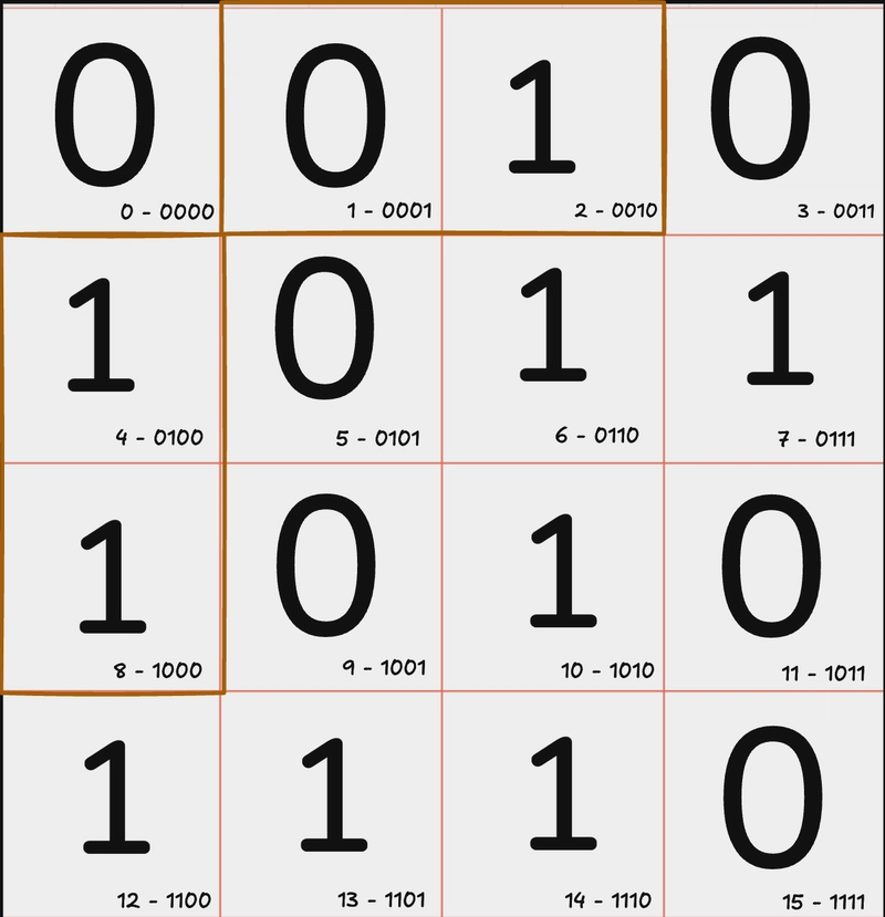
See the 4 highlighted cells? Those are our parity bits , we’ll discuss how their positions were determined later, but for now, let's focus on how we use them to detect errors.
So How do we use these 4 parity bits now? The process is similar to a simple parity check, but instead of a single parity bit verifying the entire message, each parity bit is responsible for checking a specific subset of bits.
(How are these subsets assigned? We’ll cover that soon.)
Lets take this set first

1. Parity at index 1
Here, the parity bit is at index 1, and its corresponding set of message bits is highlighted.
Running a standard parity check, we see that the number of 1s is even, meaning this subset is correct—no error detected.
2. Parity at index 2
Next, we move to the parity bit at index 2:
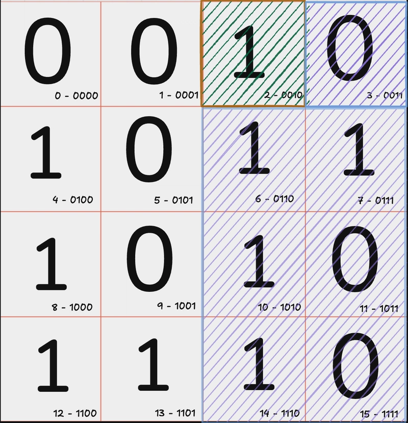
Checking parity here, we find an odd number of 1s, which indicates an error in one of these bits—but we don’t know which one yet.
3. Parity at index 4
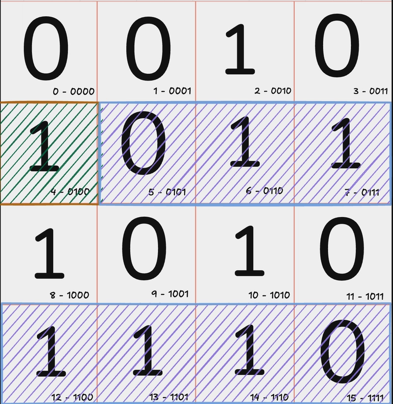
Now, let’s check the index 4 parity bit, covering the 2nd and 4th rows:
- The parity check here is even, meaning no errors were found in this subset.
4. Parity at index 8
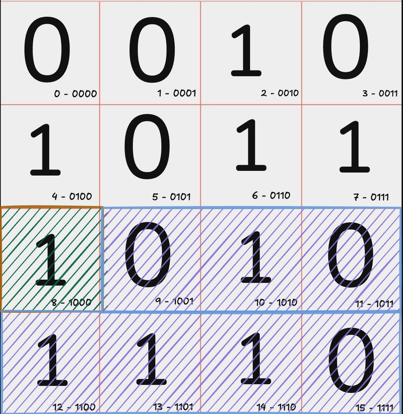
The last parity bit, at index 8, covers the 3rd and 4th rows:
- Running a parity check, we find an odd number of 1s, confirming an error in this subset as well. Pinpointing the Error
- Parity bit at index 1 verified that column 2 is correct.
- Parity bit at index 2 revealed an error in either column 1 or column 3.
- Parity bit at index 4 confirmed that the error is not in column 2, narrowing it down further.
- Parity bit at index 8 confirmed the error is in index 10.
By combining these results, we precisely locate the error bit and can correct it.
Haha, sounds like just luck, right? I mean, what if the error was one bit higher or lower? These errors happen randomly, so how can we be sure this ‘intersection’ always works? Are we just hoping for the best? So many questions!!!
Actually this above example was just to give an idea that how the algorithm works at an uber level, so that when i go in the actual intuition behind each step i can refer to the above example.
Parity Bit Placement Logic
Ok , so the parity bit's locations are not just selected randomly but are based on the property of Positional Notation (a numerical representation system where the value of a digit depends on its position in the number.)
In any positional notation system, a number is either:
- A single power of the base (if it corresponds to a pure power).
- A sum of multiple distinct powers of the base (if it is not a pure power).
For Example
Binary (Base 2)
-
8 →
1000→ ( 2^3 ) (a single power of 2) -
10 →
1010→ ( 2^3 + 2^1 ) (sum of distinct powers of 2)
Decimal (Base 10)
- 1000 → ( 10^3 ) (a single power of 10)
- 1,234 → ( 10^3 + 2 \times 10^2 + 3 \times 10^1 + 4 \times 10^0 ) (sum of distinct powers of 10)
But how did Hamming used this property?
The whole logic doesn’t rely on the values of the bits but on their positions. Hamming placed the parity bits at positions that are pure powers of 2 (i.e., 1, 2, 4, 8, …). These positions are chosen because their binary representation contains only a single 1, meaning they are not formed by summing multiple powers of 2.
But why choose only pure powers? Because every other number is just a combination of two or more pure powers of 2. For example, 9 is formed by 2³ + 2⁰, which in binary is 1001.
By reserving these pure power positions for parity bits, we can systematically group all other bits under the relevant parity checks. Any bit whose binary representation has 1 in the least significant position (i.e., xxxx1) falls under parity bit at index 1 (0001), meaning it contributes to the 2⁰ position.
However, bits do not belong to just one parity check. Since numbers are made up of multiple powers of 2, a bit like 9 (1001) falls under both parity bit at index 8 (2³) and parity bit at index 1 (2⁰).
So now, if you look at the grid above, the example images I added—and the specific set of bits assigned to each parity bit—should start to make sense. Each parity bit is responsible for checking all positions that include its corresponding power of 2 in their binary representation. This systematic assignment is what actually allows us to detect and correct errors efficiently.
At first I was a bit confused that are we sure that each number will be uniquely covered? I mean can't the combination of two parity bits point at two different message bits?
Well first of all thats not mathematically possible that exactly n pure base 2 powers will result in two different numbers i mean thats not mathematically possible.
When performing parity checks on all blocks, I can identify that errors exist in specific parity blocks (e.g., X and Y). When I XOR these parity bits, I pinpoint the exact erroneous bit.
Why? Because parity bits are derived from power-of-2 structures, meaning each parity bit corresponds to a unique set of data bits. The sum (or XOR) of two such independent parity bits always resolves to a single, unique bit position.
Mathematically, since each parity bit represents a distinct power-of-2 contribution, their combination can only result in a single nonzero bit—which directly identifies the erroneous bit. This follows from the fundamental property that the XOR of two distinct power-of-2 values always results in a unique power-of-2 value, which corresponds to a specific bit position.
But just for reference here is a table.
| Position | Binary | P1 (1) | P2 (2) | P3 (4) |
|---|---|---|---|---|
| 1 (P1) | 001 | ✅ | ❌ | ❌ |
| 2 (P2) | 010 | ❌ | ✅ | ❌ |
| 3 (D1) | 011 | ✅ | ✅ | ❌ |
| 4 (P3) | 100 | ❌ | ❌ | ✅ |
| 5 (D2) | 101 | ✅ | ❌ | ✅ |
| 6 (D3) | 110 | ❌ | ✅ | ✅ |
| 7 (D4) | 111 | ✅ | ✅ | ✅ |
Ok so if you remember now that our Index 2 and Index 8 Parity bit failed right? So how do we pinpoint the exact error bit in a more robust or mathematical way? Instead of that kind of a luck intersection way?
Well One way is to do XOR operation on the final failed parity bits which in our case are P2 and P8
Now, XOR their positions:
2 (₁₀) = 0010₂
8 (₁₀) = 1000₂
XOR: 0010₂ ⊕ 1000₂ = 1010₂ = 10 (₁₀)
This tells us that the bit at index 10 was flipped please flip it again.
This way using Hamming code we not only found that there was an error bit but also Fixed it.
Calculating the Parity Bit
Ok , we discussed the importance and maths behind the placement of the Parity bit , but what about the value of the Parity bit? Well its same as the normal Parity bit calcualtion, if in a specific set the number of 1s are even then the parity bit will be 0 otherwise 1.
Two Error Bit Detection (Extended Hamming Codes)
Now that was all about detecting and correcting a single bit , but with Hamming's algorithm we can also detect (not fix) but detect if there was one more error or not.
Remember the bit at index 0 that we ignored earlier? That bit is used for additional error detection. After correcting the first detected error, we check the bit at index 0 to see if the total number of 1s in the message is even. If it's still odd, that means there's another error somewhere in the message.
Increase in Parity bits with increase in Message bits.
It might feel concerning that how many parity bits will we need to add as the size of the message increases. Well its really negligible just to give you an idea of scale for a 256 bit message the number of parity bits used are 9 and I think thats reasonable.
The number of parity bits ( P ) required for a message of ( D ) data bits in Hamming Code follows the formula:
2p ≥ 𝐷 + p + 1
where:
- ( P ) = number of parity bits
- ( D ) = number of data bits
- The extra ( +1 ) accounts for the overall code length (data + parity).
Rationale behind this..
To detect and correct single-bit errors, each bit position must have a unique binary representation using the parity bits.
We have D data bits and P parity bits, so the total number of bits is D + P.
We need to identify errors in any of these D + P bits plus one extra case (no error).
This means we need at least D + P + 1 unique error states.
Since each parity bit combination forms a binary number, the total number of unique error states that can be represented by P parity bits is:
2p
Thus, to ensure that we can represent all possible error positions (including the "no error" case), we need:
2p ≥ 𝐷 + p + 1
This blog is heavily inspired by 3Blue1Brown’s excellent video. I highly recommend checking it out!
If you spot any mistakes or feel that something could be explained better, let me know—I’ll make sure to correct it.

Top comments (0)